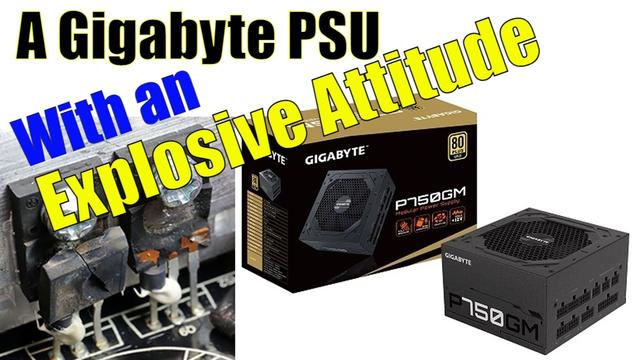
Gigabyte GP-P750GM Power Supply Review: Lacking the Explosive Character
We got our hands on an updated P750GM unit, which didn't explode during our extensive tests. While that's definitely a step up over the previous model, it's not enough, since its performance is not up to the competition's levels. This is not a unit for our best PSUs page. You'd be better off taking a look at the Corsair RM750x and the XPG Core Reactor Reactor with similar capacity.
You could find many references online to problems about the Gigabyte P750/850 GM units. TechPowerUp's unit blew, and the same was the case for several units tested by the Gamers Nexus YouTube channel. All this fuss eventually forced Gigabyte to issue a statement and take back some of these units. According to Gigabyte, the problem was due to the over power protection high setting, which was lowered in the new models. Unfortunately, there is no way to distinguish the new production P750/850GM units from the original ones. But we are certainly curious to find out the differences between the old and new platforms.
Image 1 of 12Image 2 of 12Image 3 of 12Image 4 of 12Image 5 of 12Image 6 of 12Image 7 of 12Image 8 of 12Image 9 of 12Image 10 of 12Image 11 of 12Image 12 of 12The Gigabyte GP-P750GM is a fully modular unit addressing mid-level systems. It offers Gold efficiency in the 80 PLUS program and Platinum in the Cybenetics standard. The new one has a more aggressive fan speed profile for lower internal temperatures compared to the previous generation. There are also some changes on the PCB, which we will explain in detail in the part analysis section.
Image 1 of 8Image 2 of 8Image 3 of 8Image 4 of 8Image 5 of 8Image 6 of 8Image 7 of 8Image 8 of 8Specifications
| Manufacturer (OEM) | MEIC |
| Max. DC Output | 750W |
| Efficiency | 80 PLUS Gold, Cybenetics Platinum (89-91%) |
| Noise | Cybenetics Standard++ (30-35 dB[A]) |
| Modular | ✓ (fully) |
| Intel C6/C7 Power State Support | ✓ |
| Operating Temperature (Continuous Full Load) | 0 - 40°C |
| Over Voltage Protection | ✓ |
| Under Voltage Protection | ✓ |
| Over Power Protection | ✓ |
| Over Current (+12V) Protection | ✓ |
| Over Temperature Protection | ✓ |
| Short Circuit Protection | ✓ |
| Surge Protection | ✓ |
| Inrush Current Protection | ✓ |
| Fan Failure Protection | ✗ |
| No Load Operation | ✓ |
| Cooling | 120mm Rifle Bearing Fan (D12SH-12) |
| Semi-Passive Operation | ✓ |
| Dimensions (W x H x D) | 150 x 85 x 140mm |
| Weight | 1.35 kg (2.98 lb) |
| Form Factor | ATX12V v2.52, EPS 2.92 |
| Warranty | 5 Years |
Power Specifications
| Rail | 3.3V | 5V | 12V | 5VSB | -12V | |
| Max. Power | Amps | 20 | 20 | 61 | 3 | 0.3 |
| Watts | 105 | 732 | 15 | 3.6 | ||
| Total Max. Power (W) | 750 |
Cables & Connectors
| Description | Cable Count | Connector Count (Total) | Gauge | In Cable Capacitors |
|---|---|---|---|---|
| ATX connector 20+4 pin (600mm) | 1 | 1 | 18AWG | No |
| 4+4 pin EPS12V (600mm) | 2 | 2 | 18AWG | No |
| 6+2 pin PCIe (600mm+150mm) | 2 | 4 | 18AWG | No |
| SATA (600mm+150mm+150mm+150mm) | 2 | 8 | 18AWG | No |
| 4-pin Molex (500mm+110mm+110mm) / FDD (+150mm) | 1 | 3 / 1 | 18AWG | No |
| AC Power Cord (1380mm) - C13 coupler | 1 | 1 | 18AWG | - |
The PSU has enough cables and connectors, including two EPS and four PCIe. The EPS cables should be longer, though, at 650mm (26 inches). And the SATA power connectors have a short distance between them.
Image 1 of 5Image 2 of 5Image 3 of 5Image 4 of 5Image 5 of 5
Component Analysis
We strongly encourage you to have a look at our PSUs 101 article, which provides valuable information about PSUs and their operation, allowing you to better understand the components we're about to discuss.
| General Data | - |
| Manufacturer (OEM) | MEIC |
| PCB Type | Double Sided |
| Primary Side | - |
| Transient Filter | 4x Y caps, 2x X caps, 2x CM chokes, 1x MOV, 1x Chipown PN8200 (Discharge IC) |
| Inrush Protection | NTC Thermistor 5D-15 (5 Ohm) & Relay |
| Bridge Rectifier(s) | 2x GBU1006 (600V, 10A @ 100°C) |
| APFC MOSFETs | 2x Jilin Sino-Microelectronics JCS18N50FH (500V, 11A @ 100°C, Rds(on): 0.27Ohm) |
| APFC Boost Diode | 1x JFSC0665 |
| Bulk Cap(s) | 1x Nippon Chemi-Con (400V, 680uF, 2,000h @ 105°C, KMW) |
| Main Switchers | 2x Jilin Sino-Microelectronics JCS18N50FH (500V, 11A @ 100°C, Rds(on): 0.27Ohm) |
| APFC Controller | Champion CM6500UNX |
| Resonant Controller | Champion CM6901X |
| Topology | Primary side: APFC, Half-Bridge & LLC converter Secondary side: Synchronous Rectification & DC-DC converters |
| Secondary Side | - |
| +12V MOSFETs | 4x NCE Power NCEP40T15GU (40V, 106A @ 100°C, Rds(on): 1.35mOhm) |
| 5V & 3.3V | DC-DC Converters: 4x Alpha & Omega AON6354 (30V, 52A @ 100°C, Rds(on): 3.3mOhm) PWM Controllers: 2x uPI-Semi uP9303B |
| Filtering Capacitors | Electrolytic: 1x Chn Cap (4-10,000h @ 105°C, TY), 1x Chn Cap (3-7,000h @ 105°C, TP), 4x Chn Cap (2-5,000h @ 105°C, TM), 5x YC (105°C, LE), 2x KYS (105°C, SG) Polymer: 12x no info |
| Supervisor IC | Grenergy GR8313 (OVP, UVP, SCP, PG) |
| Fan Model | Yate Loon D12SH-12 (120mm, 12V, 0.30A, Rifle Bearing Fan) |
| 5VSB Circuit | - |
| Rectifier | 1x JF Semiconductor SP10U45L-T SBR (45V, 10A) |
| Standby PWM Controller | PR8109T |
MEIC provides this platform, and although the soldering quality is good, we still found some parts from unknown manufacturers, including the filtering caps on the secondary side. Not many parts are different from the previous model, which had higher OPP and OCP thresholds. The bulk cap has changed from KMR line to KMW, and the rest of the part differences are located in the 5VSB circuit. Besides parts, there are some changes in the design of the main PCB, which we'll discuss below.
Image 1 of 6Image 2 of 6Image 3 of 6Image 4 of 6Image 5 of 6Image 6 of 6On the left is the old platform and on the right is the new one. The difference in design is located near the LLC resonant controller. The resistance of R94 has decreased, and the layout is also different. R94 is connected to the ILIM pin of the CM6901 controller, which is responsible for OPP's triggering point. If MEIC just wanted to lower OPP, there was no reason to change the layout in this area. A simple resistor replacement would do. Apparently, the company needed to tweak the design, so it decided to change the PCB.
Image 1 of 6Image 2 of 6Image 3 of 6Image 4 of 6Image 5 of 6Image 6 of 6The transient filter has all required components, including a discharge IC and an MOV. An NTC thermistor and bypass relay combo protect against large inrush currents.
Image 1 of 2Image 2 of 2The pair of bridge rectifiers can handle up to 20A of current, which is enough for this platform.
Image 1 of 4Image 2 of 4Image 3 of 4Image 4 of 4The APFC converter uses a pair of Jilin Sino-Microelectronics FETs and a JFSC0665 boost diode. Nippon Chemi-Con provides the bulk cap, and the APFC controller is by Champion.
Image 1 of 4Image 2 of 4Image 3 of 4Image 4 of 4The main FETs are installed in a half-bridge topology. An LLC resonant converter is used to boost efficiency.
Image 1 of 3Image 2 of 3Image 3 of 3Four NCE Power FETs regulate the 12V rail, and the minor rails are generated through a couple of DC-DC converters.
Image 1 of 3Image 2 of 3Image 3 of 3Less-known manufacturers provide all filtering caps on the secondary side. Thankfully, there is a large number of polymer caps, which are more tolerant to heat.
Image 1 of 3Image 2 of 3Image 3 of 3The standby PWM controller is a PR8109T IC, and the standby rectifier is a JF Semiconductor SBR.
Image 1 of 3Image 2 of 3Image 3 of 3We find four electrolytic and two polymer caps on the modular board.
The main supervisor IC is a Grenergy GR8313.
Image 1 of 7Image 2 of 7Image 3 of 7Image 4 of 7Image 5 of 7Image 6 of 7Image 7 of 7Soldering quality is good.
Image 1 of 2Image 2 of 2Gigabyte claims that the fan uses a Hydraulic bearing (HYB), but in fact it has a rifle bearing that is of lower quality. Yate Loon fans are among the cheapest.
MORE: Best Power Supplies
MORE: How We Test Power Supplies
MORE: All Power Supply Content


